Identification of Aerial or Satellite Imagery Raster Channels
New articles
GaoFen-3 SAR data processing in PHOTOMOD Radar
PHOTOMOD Radar software for Sentinel-1 data processing
The production project for the processing of more than 100,000 UAS images
Section: common questions
Source: Racurs
Author: Petr Titarov, 2019
Introduction
As the experience of everyday work shows, some photogrammetry specialists, being professionally focused on the geometric aspects of image processing, may become confused if the software they use to handle multispectral aerial or satellite imagery fails to match the raster channels to the spectral bands. This problem often occurs when new imagery products are introduced into the market and the software is not completely compliant with them or some errors have not been revealed and fixed yet. It may also be caused by the absence of the image metadata. Trying all possible channels-to-bands matches would be a rather time-consuming approach.
This article does not provide an exhaustive survey of the problem; it is merely a case study, which nevertheless may be useful as far as it considers a rather common situation, so the approach described here may be of some help if the routine workflow runs into difficulties of this sort.
Problem description
This case study considers processing a four-band (blue, green, red and near infrared) multispectral satellite image which is a part of a new imagery product (which, in fact, is still under development and has not been released yet). Immediately after the image has been imported into a digital photogrammetric system (PHOTOMOD software package) the raster looks like shown in Fig. 1.
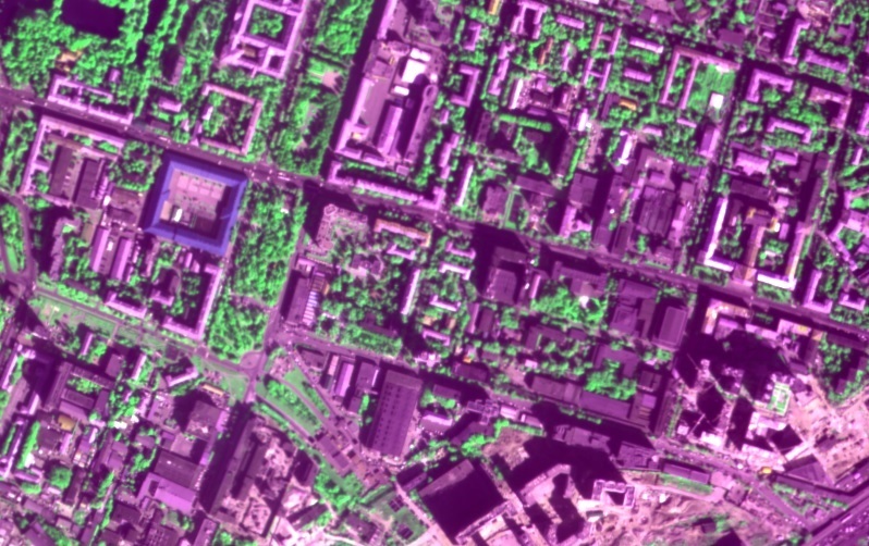
Fig. 1: The image immediately after being imported into photogrammetric software.
The default procedure applied for matching the raster channels to the spectral bands has obviously
failed. PHOTOMOD software allows the user to see the numbers of the channels assigned to the red, green and blue bands (see Fig. 2):
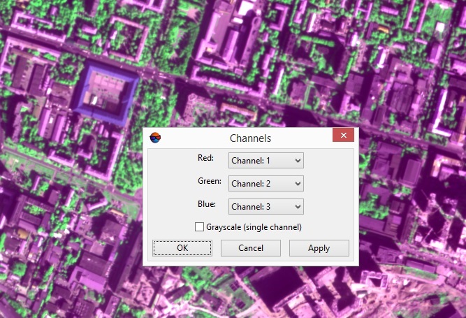
Fig. 2: The raster channels assigned to the spectral bands by default.
At first glance it may seem that the channel number for the green band is assigned correctly as far as the foliage is displayed in green; its unnatural shade may be accounted for by the channel mismatch for other bands. But let us avoid hasty judgments.
Spectral bands identification
Let us look at a fragment of the image which contains vegetation and set all the three color raster channels (red, green and blue) to display the same spectral band - for each band by turns. Fig. 3 shows it for the spectral band corresponding to raster channel 1:
Fig. 3: Setting all three colour raster channels to display the same spectral band.
It is needless to say that the image will be looking grayscale - but not the same for different spectral bands.
Let us compare the grayscale rasters corresponding to different channels/spectral bands:
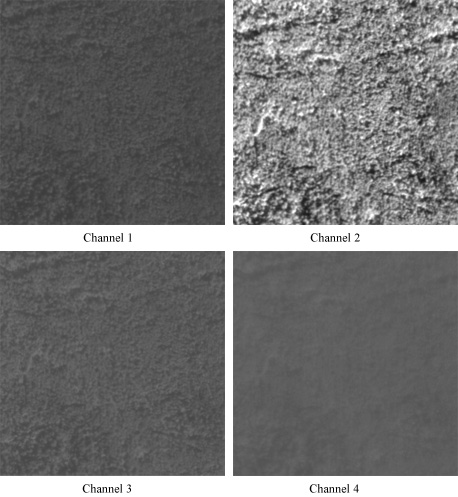
Fig. 4: Vegetation displayed in different channels.
Firstly, the raster corresponding to channel 4 evidently is the most blurred one. Under the meteorological conditions the imagery is acquired the blurring is caused by Rayleigh scattering; the shorter the wavelength the stronger is the scattering, therefore, it is the blue band which is most affected by it (it is commonly known that this type of scattering makes the clear sky blue). So channel 4 quite likely corresponds to the blue spectral band.
Secondly it leaps to the eye that vegetation looks the brightest in the raster corresponding to channel 2.
It might be assumed that vegetation which looks green to us should be the brightest in the green spectral band. But let us remember the limitations of human vision and consider the diagram describing vegetation spectral reflectance (see Fig. 5):
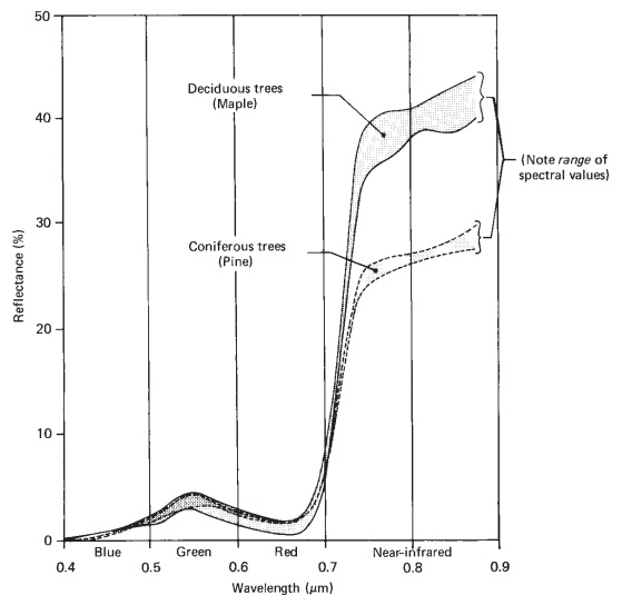
Fig. 5: Generalized spectral reflectance envelopes for deciduous (broad-leaved) and coniferous (needle-bearing) trees (adapted from [3], Fig. 1.7, page 14).
The diagram shows that vegetation reflectance in the green band is somewhat higher than in red and blue ones, but in terms of quantity the difference between all the three color bands is fairly small as compared to much higher reflectance value in the near infrared band!
On the other hand, at the surface of the Earth solar radiance in the near infrared spectral band is significantly lower than in the green one (see Fig. 6):
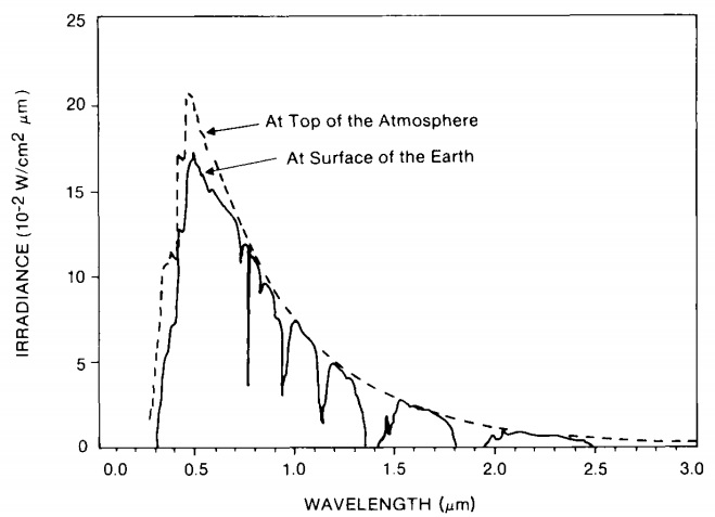
Fig. 6: Solar spectral radiance as a function of the wavelength at the top of the atmosphere and at the surface of the Earth (adapted from [2], Fig. 1.3, page 11).
Hence although there are some reasons to conclude that channel 2 corresponds to the near infrared band it would be a good idea to provide another evidence for this conclusion. For this let us find in the image some water bodies whish should look dark in the near infrared band as far as the reflectance of water in this band is significantly lower than in the visible range (see the dotted line in Fig. 7):
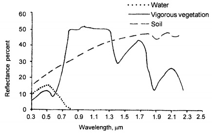
Fig. 7: Spectral reflectance curves or spectral signatures of typical features of earth's surface (adapted from [1], Fig. 2.15, page 47).
In the same way we did it before let us produce the rasters showing the water body in different channels:
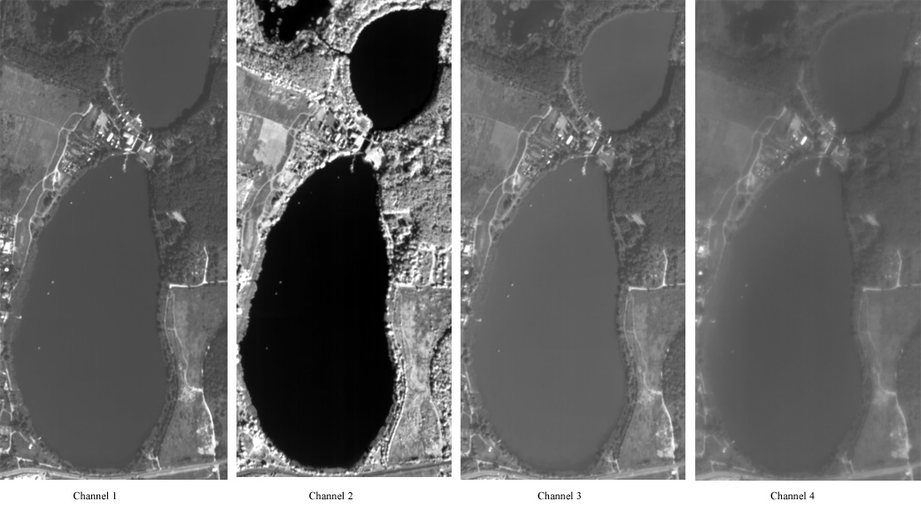
Fig. 8: A water body displayed in different channels.
In the channel 2 raster the water body looks much darker than in other channels while the brightness of the surrounding vegetation is much higher. Moreover, even in the downscaled fragments shown in Fig. 8 we can see that the image representing channel 4 (which most probably corresponds to the blue band) is the most blurred one while channel 2 image is the sharpest - this fact, taking into account the Rayleigh scattering, also suggests that channel 2 corresponds to the longest wavelengths available in the multispectral image - in other words, to the near infrared band.
So channels 2 and 4 most probably contain the near infrared and blue band data respectively. Considering the other two channels, channel 1 and channel 3, the latter one seems to correspond to the green band as far as vegetation looks brighter in it than in channel 1 (see Fig. 4). So if channel 3 is assumed to be green, channel 1 has to be red. It should be noted that this channel numbering is neither common nor self-evident.
Verification of raster channels identification
To check the conclusions we have come to, let us set the software to display channels according to our findings: channel 1 data as red, channel 3 data as green and channel 4 data as blue. Very convenient objects for the verification are stadiums: during the imagery acquisition season the football field is usually green and the race tracks around it are red. Although sometimes the colors are different (for example, the race tracks may be black), they do not vary as widely as the color of roofs which can be gray, red, blue, green and so on...
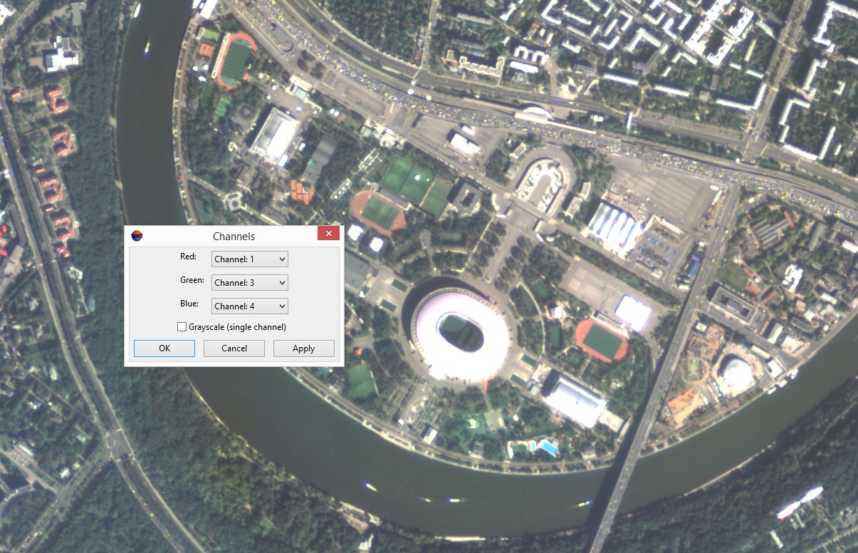
Fig. 9: Stadiums in the raster displayed according to the found channels-to-bands matching.
In the Fig. 9 we can see that the stadiums are displayed in the right colors, vegetation is green and its shade seems to be quite natural and other objects look natural as well.
In case the image covers an undeveloped area and there are not enough human-made objects for reliable verification one can make use of Google Earth service. The author once came across an image which seemed to be looking quite unnatural but actually it was the true colors of a landscape in South America.
Besides that, most imagery products include a quicklook file which can be used to check whether the image is displayed correctly.
Fig. 10 below shows the same raster fragment as Fig. 1 to compare the correct channels-to-bands matching with the default one.
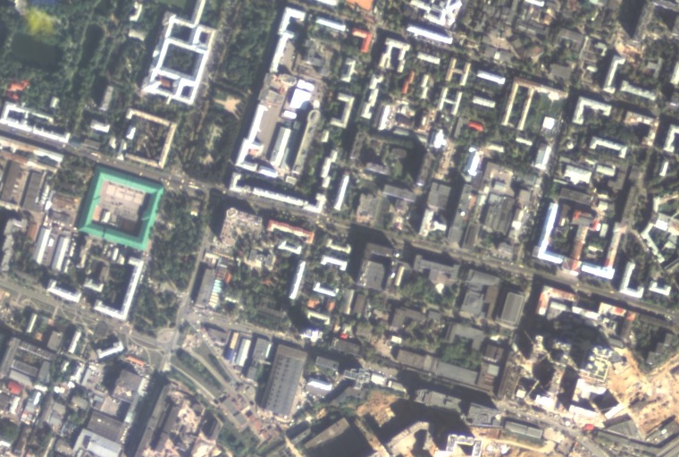
Fig. 10: The raster shown in Fig. 1 after channels-to-bands matching correction.
Conclusion
The following procedure to match the channels of a four-channel multispectral aerial or space image to the spectral bands (blue, green, red and near infrared ones) is proposed:
1. Display a fragment of the image covering vegetation in each channel separately. The channel of the most blurred raster is likely to correspond to the blue spectral band, the channel of the brightest raster most probably belongs to the near infrared band; the brighter of the other two rasters corresponds to green and the remaining one - to the red band.
2. Examining the vegetation it is possible to confuse the green band with the near infrared one, so for reliable identification of the near-infrared band it is useful to display a water body in each channel separately. It will be looking the darkest in the near-infrared band.
3. Very convenient objects for the verification of channels-to-bands matching are stadiums; besides that one can make use of Google Earth service or the quicklook included in most imagery products.
References
1. Anji Reddy M., Textbook of Remote Sensing and Geographical Information Systems,
3rd ed., Hyderabad: BS Publications, 2008.
2. Chen H.S., Space Remote Sensing Systems: An introduction.: Academic Press, 1985.
3. Lillesand T.M., Kiefer R.W., Chipman J.W., Remote Sensing and Image Interpretation, 7th ed.: Wiley, 2015.


